Carbon nanotubes grow because a metal catalyst particle, usually iron, cobalt, or nickel, breaks apart a carbon-containing gas, dissolves the carbon atoms, reaches a saturation point, and then precipitates that carbon as a curved graphene cap that lifts off and extends into a hollow tube. That sequence: decompose, dissolve, saturate, nucleate, grow, is the engine behind every CVD nanotube you have ever seen. If any one step fails, you get no tubes, short tubes, or a clump of amorphous carbon instead.
Why Carbon Nanotubes Grow: Mechanisms, Conditions, Fixes

Marcus Whitmore
18 May 2026
What 'growth' actually means for a carbon nanotube
For a biological cell, growth means adding mass through metabolism. For a nanotube, growth means extending a hollow cylinder of sp2-bonded carbon one atomic ring at a time. The tube does not grow from the middle; new carbon is added only at the open edge sitting on or near the catalyst particle.
Think of it like a factory where the raw material (carbon feedstock gas) feeds into one end of the machine (the catalyst particle), gets processed, and exits as a product (the growing nanotube wall) from the other side. The 'atom-to-tube-length' journey goes: gas-phase carbon precursor molecules arrive, the catalyst surface tears them apart, individual carbon atoms dissolve into or diffuse across the metal nanoparticle, and then those atoms slot into the hexagonal lattice at the tube's growing edge.
Repeat that millions of times per second and you get a tube that can reach hundreds of micrometers or even millimeters in length. That is growth in nanotube terms.
It is worth noting that this process has a lot in common with how crystals grow from solution: you need a source of building blocks, a surface on which they can organize, and a thermodynamic driving force to keep them adding up. The difference is that nanotubes are kinetically steered into one specific geometry by the catalyst particle, and the geometry is locked in at the very first moment of nucleation. This is why the catalyst is so much more than just a 'helper'; it is the architect.
The core driving forces: what actually pushes carbon into a tube shape

There are four interlocking forces at work. Understanding each one separately makes troubleshooting much easier.
Catalyst-driven decomposition
The metal nanoparticle is first a cracking machine. When a hydrocarbon molecule like methane, acetylene, or ethanol lands on its surface, the metal breaks C-H bonds at temperatures where the gas alone would be stable. This is the catalytic step that generates the free carbon atoms (or small Cn clusters) that everything else depends on. Without it, your feedstock just flows through the reactor without contributing to growth.
Carbon dissolution and supersaturation
Once cracked, carbon atoms dissolve into the metal particle, this is especially efficient in high-carbon-solubility metals like nickel. The particle loads up with carbon until it crosses a saturation threshold. This is directly analogous to dissolving sugar in warm water: below saturation, everything stays in solution. Above it, something has to crystallize out. For carbon in a metal nanoparticle, what crystallizes out is graphitic carbon. The higher the carbon chemical potential (more feedstock, less hydrogen, higher temperature), the faster supersaturation is reached and the faster growth can initiate.
Nucleation: the hardest step
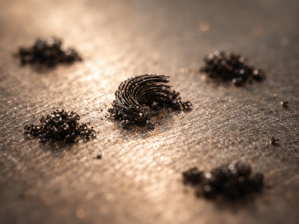
Nucleation is where the carbon decides it is going to become a nanotube rather than a blob of amorphous soot. On a nickel catalyst surface, for example, a graphene embryo forms between opposing step edges on the particle's faceted surface. The step edges migrate, guide the embryo into a curved shape, and if the symmetry across adjacent facets is preserved, the embryo becomes a cap. That cap is the critical precursor. If the cap does not form correctly, if the curvature symmetry is broken, you get encapsulating graphitic carbon (the particle gets wrapped up and killed) instead of a growing tube. This is one of the most common silent failure modes in nanotube synthesis.
Carbon incorporation and cap lift-off
Once the cap forms, the real growth begins when additional carbon species incorporate at the cap's open edge. Density functional theory calculations show this edge incorporation is what lifts the cap off the particle surface and converts it from a hemispherical graphene dome into a growing tube. After lift-off, the process becomes self-sustaining as long as the carbon supply and catalyst activity are maintained. The two pathways after initial decomposition, bulk diffusion through the particle versus surface diffusion over it, depend on how much hydrogen is still attached to carbon at the time; both can lead to nanotube growth, but they operate at different rates and can favor different tube types.
The conditions that have to be right
Every factor below is a dial. Turn any one too far in the wrong direction and growth fails. Here is what each one does and why it matters.
| Condition | Typical range / target | What goes wrong if it's off |
|---|---|---|
| Temperature | 600–1000 °C depending on feedstock and catalyst | Too low: insufficient decomposition, no supersaturation. Too high: catalyst sintering, uncontrolled amorphous carbon deposition |
| Carbon feedstock type | CH4, C2H2, CO, alcohols, etc. | Wrong choice for catalyst/temperature combo suppresses cracking or drives coking |
| Carbon feed rate / partial pressure | Tuned to match catalyst cracking capacity | Too fast: oversaturates catalyst, causes encapsulation. Too slow: no supersaturation, no nucleation |
| Hydrogen / etching gas | H2 co-fed or in situ from decomposition | Too little: amorphous carbon accumulates. Too much: carbon chemical potential drops, growth stalls |
| Gas flow rate and pressure | Reactor-specific; determines boundary layer thickness | Poor flow → mass transport limited growth, short tubes, poor uniformity |
| Water vapor (optional but powerful) | Trace levels (e.g., water-assisted 'super-growth') | Too much or wrong timing: over-oxidizes catalyst or disrupts nucleation. Right amount: removes amorphous carbon, extends catalyst lifetime |
Temperature deserves special attention. It controls how fast the feedstock decomposes, how much carbon the catalyst particle can hold in solution, and whether the catalyst stays as a useful nanoparticle or sinters into a useless blob. For small iron clusters, the minimum temperature for effective growth is actually higher than you might expect from bulk thermodynamics, because carbon solubility drops as particle size decreases. That means if you are working with very small catalyst particles to target narrow-diameter SWCNTs, you may need to raise your growth temperature rather than lower it.
The hydrogen balance is similarly underappreciated. Hydrogen from feedstock decomposition etches away amorphous carbon from the catalyst surface, keeping active sites open. Too little hydrogen and the catalyst gets buried. Too much and you suppress the carbon chemical potential below what is needed for nucleation. This balance is one of the reasons water-assisted CVD works so well: a trace of water acts as a mild oxidizing agent that removes amorphous carbon from catalyst surfaces, dramatically extending catalyst lifetime and producing forests up to 2.5 millimeters tall in the famous super-growth results.
How the catalyst controls tube diameter and chirality
The catalyst particle is not just a decomposition site, it is the mold for the tube. Particle size sets tube diameter: smaller particles template narrower tubes. Particle composition and state (solid intermetallic versus liquid-like molten metal) strongly affect which chiral angles are favored.
A recent review of SWCNT growth modes emphasizes that catalyst structure and temperature influence carbon incorporation pathways and chirality selection, with comparative chiral-angle distribution measurements on solid intermetallic Co7W6 versus molten monometallic catalysts under CO carbon feeding showing how thermodynamics and kinetics jointly shape (n,m) populations [Particle composition and state (solid intermetallic versus liquid-like molten metal) strongly affect which chiral angles are favored. ](https://pmc. ncbi. nlm.
nih. gov/articles/PMC9565797/). Solid intermetallic catalysts like Co7W6 produce a narrower chiral angle distribution than molten monometallic catalysts like pure Fe or Ni, because the crystallographic step-edge structure of the solid particle constrains which cap geometries can nucleate. In molten particles, that constraint is relaxed and you get a broader, more random chiral distribution.
Practically, this means chirality control requires controlling catalyst state. If you want selective (n,m) populations, you need to engineer the catalyst composition, particle size, and temperature so the particle stays in a defined structural state during nucleation. Changing the CO flow rate at a fixed temperature on Co nanoparticles, for example, has been shown experimentally to shift chiral angle distributions measurably. One experimentally documented example is that SWCNT chirality selection varies with CO flow rate at 650°C on quartz-supported Co nanoparticles, shifting the chiral angle distributions. Carbon feed rate is a chirality knob, not just a yield knob.
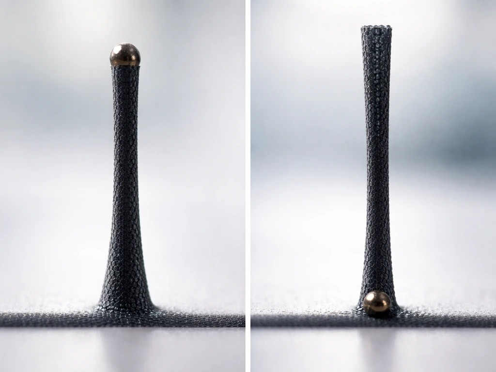
Particle size also determines growth mode through a mechanical effect: larger particles tend to have weaker adhesion relative to the upward force of the growing tube, so the particle lifts with the tube (tip growth). Smaller particles adhere more strongly to the substrate and stay put while the tube grows upward (base growth). This size-dependent switch has real consequences for process design.
Tip growth vs base growth: what they are and how to tell them apart
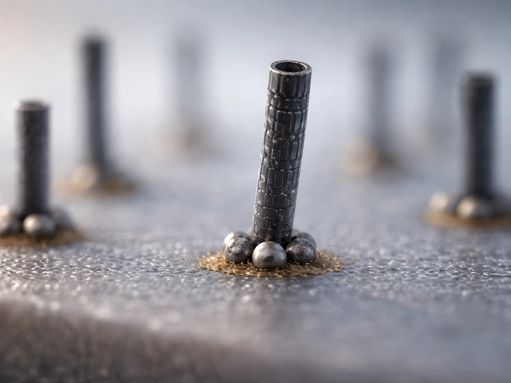
In tip growth, the catalyst particle rides at the top of the growing tube, lifted off the substrate as carbon precipitates below it. The substrate end of the tube is closed and anchored; the growing edge is up top with the metal. In base growth, the catalyst stays on the substrate. The tube lifts up from a base while the catalyst remains fixed, and new carbon is incorporated at the tube-catalyst interface at the bottom. Both modes produce nanotubes, but they behave differently in process design, especially for vertically aligned forest growth.
The simplest way to identify which mode is operating is to look at where the catalyst ends up after growth. If you find metal nanoparticles at the tips of the tubes (visible by TEM or energy-dispersive X-ray), it is tip growth. If the catalyst stays on the substrate and the tube tops are clean, it is base growth. Experiments with cobalt/alumina catalysts in water-assisted acetylene CVD have shown gradual deceleration followed by sudden termination that is consistent with base-growth dynamics where catalyst activity at the substrate interface is the controlling factor. For methane decomposition on nickel-containing catalysts at around 800 °C, tip growth with catalyst encapsulation is frequently observed.
Why growth stops
This is the question that most people do not think about until their tubes stop growing shorter than expected. Growth stops for one of four reasons, and they are not always easy to distinguish from each other.
Catalyst deactivation and coking
The catalyst surface gets buried. Amorphous carbon or graphitic shells deposit on the metal particle, blocking active sites. This is coking, and it is the most common growth killer in methane and acetylene CVD. That same idea also helps explain why crystals can form on charcoal when carbon is deposited and conditions favor ordered graphitic growth crystals form on charcoal. Once a particle is fully encapsulated by a graphitic shell, it is chemically dead, carbon can no longer dissolve into it, and growth stops. The encapsulation can happen in minutes under high-carbon-flux conditions. This is why the hydrogen/etching balance is so important: etching gases (H2, H2O, CO2) remove amorphous carbon faster than it deposits, keeping the particle surface active.
The growth-vs-etching dynamic equilibrium
Even on an unencapsulated catalyst, there is a dynamic competition between forward carbon incorporation (growth) and reverse graphene etching. As the graphene adlayer on the catalyst surface grows, it can spontaneously switch from the growth regime to the etching regime if coverage crosses a threshold. This is not a slow process, it can happen abruptly, which explains why some vertically aligned CNT forest experiments show sudden termination even when feedstock is still flowing abundantly. The tube does not know the gas is still there; the surface reaction has reversed.
Mass transport limitations
As tubes grow taller, the gas-phase reactant has to travel farther through a thickening forest to reach the active catalyst. Boundary layers develop, and eventually the rate of reactant delivery to the catalyst falls below what is needed to sustain growth. At that point, you are not kinetics-limited anymore, you are transport-limited. Increasing your feed flow rate can help push through this, but only up to a point. Once the boundary layer is thick enough, adding more gas just improves uniformity in the upper part of the forest without reaching the base. This is a practical ceiling on tube length in dense forests.
Thermal and structural limits
At high enough temperatures, catalyst particles sinter: they merge together, grow larger, and lose the size-controlled properties that made them useful. Sintered particles produce larger-diameter, lower-quality tubes or stop producing tubes entirely. There are also mechanical forces within a growing CNT forest, compressive stresses build as the forest densifies, and these can contribute to termination by physically disrupting the catalyst layer or cracking the tube array.
Practical troubleshooting: diagnosing what is going wrong in your reactor today
The failure modes above translate into specific, diagnosable symptoms. Here is how to work through them systematically.
No tubes at all: nucleation failure
If you see no tubes or only amorphous carbon deposits, the most likely culprits are: temperature too low for your feedstock/catalyst combination (insufficient decomposition), carbon chemical potential too low (too much hydrogen dilution), catalyst particles too large (diameter mismatch), or the nucleation window (the induction period where carburization and cap formation happen) being missed because you ramped to growth temperature too fast or slow.
Alum crystals grow by a different crystallization pathway, but many of the same ideas about supersaturation, nucleation, and how impurities or conditions disrupt growth still apply why do alum crystals grow. If you’re wondering whether your cermet is going to grow, the answer depends on whether nucleation and the growth-etching balance will stay in your favor is your cermet going to grow. Check whether your catalyst is being pre-reduced properly before carbon feed begins.
On Ni-Mg-Al catalysts in methane CVD, for example, there is a documented induction period of carburization before nucleation occurs, if you are cutting that short, you will never enter the growth phase.
Low yield or sparse tubes
If tubes are forming but yield is poor, the issue is usually either too few active catalyst sites (catalyst loading or dispersion problem), early encapsulation (increase etching gas or add trace water), or transport starvation (improve flow uniformity, increase gas velocity, or check for dead zones in your reactor). Raman spectroscopy is your fastest diagnostic tool here: a high D/G band ratio (D band around 1340-1350 cm-1, G band around 1590-1600 cm-1) tells you there is significant disorder and defect formation, pointing toward carbon quality issues rather than a yield/density problem.
Short tubes or abrupt growth termination
Short tubes in a process that used to give longer ones usually mean catalyst deactivation got faster, check whether your feedstock purity changed (sulfur contamination is a classic catalyst poison) or whether your carbon/hydrogen ratio drifted. For forest growth where termination is sudden rather than gradual, you are likely seeing the growth-etching reversal mechanism: the catalyst coverage tipped over into the etching regime. Reducing carbon partial pressure slightly or introducing a mild oxidizing agent (trace H2O or CO2) can restore the balance. If the termination is gradual and correlated with forest height, you are transport-limited: work on reactor geometry, flow rate, or try a moving-substrate approach that continuously refreshes the gas environment at the catalyst surface.
Poor chirality control or random diameter distribution
Random chirality almost always means your catalyst particles are not in a well-defined structural state during nucleation. Check particle size distribution (TEM before growth), verify that your growth temperature is in a range where the catalyst has a known and consistent phase (solid intermetallic vs liquid-like), and consider switching to a more selective catalyst system (Co7W6 for solid-state selectivity, for example). Also remember that carbon feed rate is a chirality lever: if you can measure RBM modes in Raman at low excitation energy and see a broad distribution, try modulating your carbon flow rate at fixed temperature to see if the distribution shifts. That tells you whether your problem is kinetic (fixable by process parameters) or structural (requires catalyst reformulation).
A practical checklist before your next run
- Verify catalyst particle size and dispersion by TEM or SEM before growth — size determines both diameter and growth mode.
- Confirm your growth temperature is above the minimum nucleation threshold for your catalyst/feedstock pair, especially if using small particles.
- Set up a defined pre-reduction or catalyst activation step before carbon feed begins; do not skip the induction period.
- Tune your hydrogen-to-carbon ratio first to find the window between 'too much amorphous carbon' and 'carbon chemical potential too low.'
- If adding water, introduce it after catalyst stabilization, not at the start; timing matters for whether water helps or hurts.
- Run a Raman scan on your product to get the D/G ratio and look for RBM features; use this as your baseline before changing any other variable.
- If tubes are short, diagnose transport vs deactivation by testing shorter growth times: if early growth rate is high but slows quickly, it is deactivation; if it is slow from the start, it may be transport or nucleation.
- Locate catalyst particles after growth (tip vs base) to confirm which growth mode is operating before making adjustments to substrate or flow geometry.
Carbon nanotube growth is, at its core, a constrained self-organization process, the same framing that applies to crystal growth, biological cell growth, or any system where building blocks are driven by thermodynamics to assemble into ordered structures but stopped by kinetic and physical limits. Under metamorphism, recrystallization and grain growth can lengthen grains as new mineral domains form and boundaries migrate recrystallization during metamorphism causes grains to grow longer in the. The catalyst sets the structure.
Supersaturation provides the driving force. Nucleation commits the geometry. And deactivation, transport, and etching define how long the process can run. Once you see the mechanism that clearly, every knob in your reactor has a logical place in the picture, and troubleshooting stops feeling like guesswork.
FAQ
Why do my CNTs stop completely right after I switch on the carbon feed, even though the reactor looks correctly set?
You usually cannot start with carbon feed alone. Many catalyst systems need a pre-conditioning step (for example, reduction or carburization in a short induction period) so the nanoparticle is in the right active state before growth begins. If you skip this, you may see carbon only depositing as amorphous soot because nucleation never enters the cap-forming window.
How do I choose the “right” hydrogen or water level without accidentally suppressing nucleation?
Small changes to the hydrogen-to-carbon balance can be the difference between active growth and rapid encapsulation. If you add too little hydrogen (or water), you increase coking rate on the particle surface. If you add too much, you can suppress the carbon chemical potential so cap nucleation is hindered. A practical approach is to tune hydrogen (or trace water) in small increments while monitoring catalyst deactivation time, not just final yield.
What is the fastest way to tell whether my process is tip growth or base growth?
The strongest practical indicator is where the catalyst ends up, not how tall the tubes look. Use TEM (or EDS mapping) to check whether metal nanoparticles remain at the tube tips or stay near the substrate. Tip growth and base growth also imply different failure timing, for instance base-growth termination often correlates with substrate-interface activity fading as the process runs.
Why do I get random chirality even when my diameter distribution looks reasonable?
Yes. Random or mixed chirality often comes from the catalyst being in an ill-defined phase or structure during nucleation, not just from “bad tuning.” Check catalyst particle size distribution and whether your temperature window keeps the catalyst in the intended structural state (solid intermetallic versus liquid-like). Also consider that chirality shifts can track carbon feed rate, so test carbon flow changes at fixed temperature rather than changing temperature first.
What should I try first if my CNTs are high-quality but much shorter than expected?
No single ratio guarantees long tubes. You need to keep three things simultaneously in the favorable regime: enough carbon chemical potential for nucleation and continued edge incorporation, enough etching action to prevent coking, and enough reactant delivery to the base of a forest. If your tubes get short but still show good quality, transport limitation is a common cause, so increasing flow or improving flow uniformity can outperform further hydrogen/carbon tweaking.
Why does increasing gas flow extend the forest height a bit, then stops helping, even though feedstock is still present?
Yes, especially for dense vertically aligned forests. When the forest thickens, boundary layers make the delivery of reactants to the base rate-limiting, so adding more overall flow can help only up to a ceiling where uniformity improves near the top but the base still starves. You can diagnose this by correlating termination height with time and by checking whether changing reactor geometry or gas velocity shifts the maximum achievable height.
My forest terminates abruptly (sudden cutoff). How can I tell if it is coking versus transport limitation?
Coking and graphene encapsulation can cause abrupt termination even while carbon feed continues, because the catalyst becomes chemically dead once fully wrapped. A telltale sign is that growth ends suddenly across the bed, and post-run imaging shows graphitic shells or encapsulated particles. This points to etching being too weak relative to deposition, often fixed by adjusting hydrogen or adding a mild oxidizing component like trace water or CO2.
How should I interpret a high Raman D/G ratio when trying to improve yield and length?
Use your “fastest diagnostic” idea from Raman more deliberately. A high D/G ratio signals disorder and defect-rich carbon, which often means the process is spending more time in deposition or etching-misaligned regimes, not necessarily that you have too few tubes. For troubleshooting, compare Raman quality metrics across runs while keeping catalyst loading constant, so you can distinguish carbon-quality problems from true yield limitations.
If only my feedstock source changed, why would my CNT growth degrade even though reactor settings are identical?
Common poison sources include sulfur-bearing impurities, oxygen-containing contaminants, and unexpected changes in feedstock composition. Even if your growth temperature and gas flows are unchanged, a shift in feed purity can shorten catalyst life, leading to shorter tubes or lower yields. The practical step is to verify mass-flow controllers and gas cylinders or liquid feed preparation, then look for early deactivation timing changes.
Can changing carbon feed rate improve chirality selectivity, or does it only change tube density?
Changing CO (or any carbon-containing feed) at fixed temperature can alter the chiral angle distribution because it changes how quickly carbon chemical potential rises and how the catalyst passes through nucleation. If your goal is chirality selection, do not treat carbon feed rate as only a “yield knob.” Instead, run a small matrix of carbon flow values while monitoring Raman radial breathing modes at the same excitation conditions to see whether the distribution actually shifts.
Next Article
Is Your Cermet Going to Grow? Causes, Tests, Fixes
Understand what makes cermet growth happen, how to test today, and which fixes prevent halted growth or degradation.